Variable Frequency Drive for Constant Pressure Water Supply
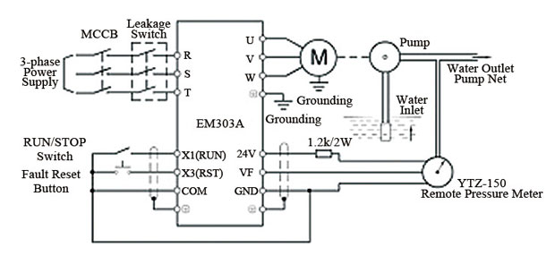
In water supply system, constant pressure water supply refers to the control mode which controls the outlet pressure within the setting value by detecting the pipe and network pressure when the water amount in the pipe and network changes. Usually, when selecting water pump, its rated flow is bigger than the actual flow, and the flow varies a lot when in use, for example, in buildings water supply, the water consumption between day and night varies a lot, valve regulation mode is commonly used. Even the method is simple, however, it is regulated by increasing of resistance manually that results in a lot of waste in electricity and high maintenance required. Variable frequency AC drive introduced here with built-in PID to perform the automatic constant pressure water supply for saving energy.VFD for constant pressure water supply wiring:

As illustrated on the wiring diagram, connect with air switch, leakage switch and power, after finishing wiring detection, the air switch is turned on, variable frequency drive is connected, 0.0 shows on the LED.
When the power is turned off, re-connect motor, start/stop switch, remote manometer, and current-limiting resistor, and check if the variable frequency drive and motor is well grounded.
YTZ-150 potentiometer remote manometer is selected, and installed on the outlet pipe of the water pump. The manometer is applicable to regular manometer working condition, which could not only directly measure the value of pressure, but also outputs corresponding electrical signal to the remote controller. There are red, yellow and blue 3 extension wires of manometer.
The Electric Parameter of Manometer:
1. Full scale of resistor: 400Ω(Blue and red)
2. Initial resistor value at zero pressure: ≤20Ω (Yellow and red)
3. Resistor volume at full-scale upper limited pressure: ≤360Ω (Yellow and red)
4. Terminal block external voltage: ≤6V (Blue and red)
Open Loop Commissioning:
Check the wiring is well connected, turn on the air switch and leakage switch, the variable frequency drive is electrified 0.0 shows LED. Press JOG button to check the rotation direction of water pump, if reverse, change the phase sequence of motor.
Press RUN button, the indicator turns green, turn the knob on the keypad clockwise.
The output frequency goes up, observe the indicator on the manometer, and check the voltage value between terminals VF and GND on the variable frequency drive by using multi-meter.
The voltage increases with the increase of output frequency and pressure, the feedback voltage between VF and GND increases, record the feedback voltage value corresponding to the expected constant pressure, for example: 5kgs. Press STOP button, the VFD drive decelerates to stop.
VFD parameters setting:

Closed Loop Variable Frequency Constant Pressure Running
Switch-on the start/stop switch, the indicator is on, when the output frequency changes from 0 to 30 Hz, auto-regulation based on the actual water consumption to ensure the outlet pressure is 5kg. Increase the parameter of F7.04, the outlet pressure goes up, vice versa, the pressure goes down.


